
Overview
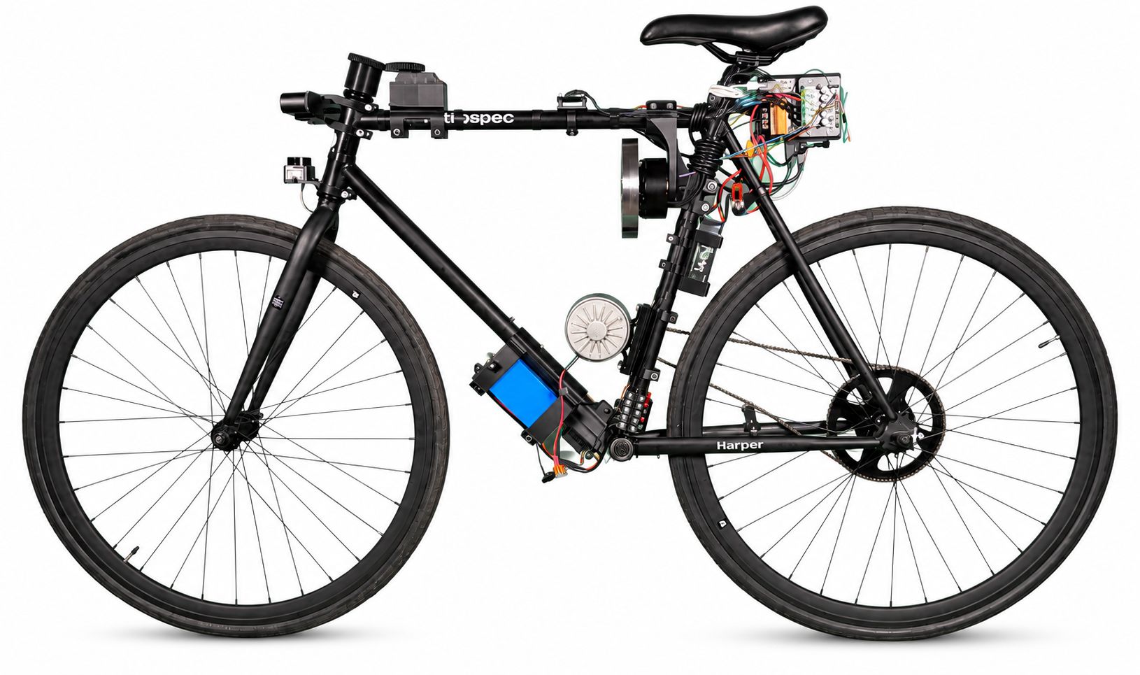
A stationary bicycle behaves like an inverted pendulum. Steering-based stabilization only works above a minimum speed, which rules it out for a bike that needs to hold position or start from rest. Our approach uses a reaction wheel: a spinning steel disk mounted to the frame that generates corrective torque by accelerating against any lean, independent of forward velocity.
This was a 3-person ISR (Independent Study and Research) course project. I owned the electrical architecture, STM32 firmware, controller implementation, and system integration, and contributed to CAD mounts for the reaction wheel, IMU, and electronics. The balancing subsystem maintains stationary upright balance indefinitely under normal test conditions.
My Contributions
- Designed the electrical architecture and power-domain separation across balancing, drive, and navigation subsystems
- Wrote bare-metal STM32 firmware in C: IMU sampling, complementary-filter angle estimation, PID control, safety shutoff, and UART torque commands to the ODESC motor controller
- Debugged USB clock misconfiguration (PLL recalculation for 25 MHz oscillator), SPI mode mismatch on the IMU, and motor-controller direction-switching limitations
- Selected and integrated the reaction-wheel motor, magnetic encoder, ODESC V4.2, IMU, and power system
- Contributed to OnShape CAD models and 3D-printed mounts for the IMU, electronics, and reaction-wheel assembly
System Architecture
The platform is split into three subsystems, each with its own power domain and compute.
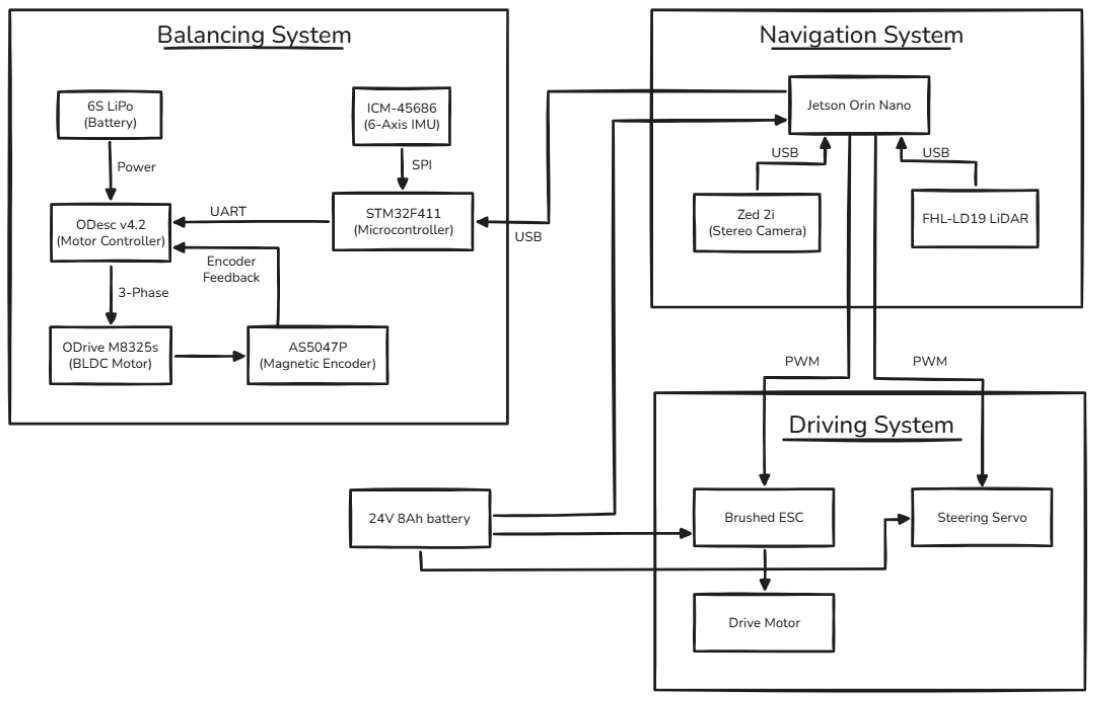
Balancing System: STM32F411 reads the ICM-45686 at 400 Hz, estimates lean angle, runs the PID loop, and sends torque commands to the ODrive M8325s via the ODESC V4.2 controller. Powered by a dedicated 6S LiPo.
Driving System: A brushed DC motor drives the rear wheel through an 8.2:1 chain reduction. A 160 kg-cm servo controls the front fork. Both are controlled via PWM.
Navigation Hardware: A Jetson Orin Nano, ZED 2i stereo camera, and 2D LiDAR are mounted to the frame. These were part of the original project scope; autonomous navigation was not implemented in this build.
| Subsystem | Key Components |
|---|---|
| Balancing | STM32F411, ICM-45686, ODrive M8325s, ODESC V4.2, AS5047P, 6S LiPo (22.2V) |
| Driving | Brushed DC motor, 110A ESC, 160 kg-cm servo, 24V 8Ah Li-ion |
| Navigation hardware | Jetson Orin Nano, ZED 2i stereo camera, 2D LiDAR |
Balancing Controller
The balancing controller is the core of the project. It runs as a bare-metal superloop at 400 Hz on the STM32, no RTOS. Every 2.5 ms: read IMU, estimate angle, compute PID output, send torque command.
IMU Sensing and Angle Estimation
The ICM-45686 communicates over SPI at 7.5 Mbps, streaming gyroscope and accelerometer data at 400 Hz. Gyro range is ±125 dps and accelerometer ±4g, sized for the expected lean dynamics.
Angle estimation uses a complementary filter that blends both sensor modalities:
angle = 0.98 * gyro_angle + 0.02 * accel_angleThe gyroscope integrates angular rate accurately over short intervals but drifts over time. The accelerometer gives an absolute gravity-referenced lean angle but is corrupted by vibration. The 98/2 weighting keeps the estimate gyro-dominant for fast dynamics while letting the accelerometer slowly correct drift. A third-order low-pass filter with roughly 6 Hz bandwidth pre-conditions accelerometer data before fusion to suppress motor vibration.
The IMU is mounted on M3 anti-vibration rubber standoffs to mechanically decouple it from reaction-wheel vibration.

PID Control Loop
The controller outputs a torque command in Nm, sent to the ODESC V4.2 over UART. Torque mode bypasses the ODESC's internal velocity loop, giving the PID direct authority over reaction-wheel angular momentum.
Derivative on measurement is used: the raw negated gyro rate feeds the D term directly rather than differencing error values. This avoids derivative spikes when the setpoint changes.
Gains were tuned through a structured process:
- P-only control with increasing gain until sustained oscillation. Critical gain:
Kp_critical ≈ 850 - Ziegler-Nichols closed-loop rules gave initial P, I, and D values
- Manual refinement settled on
Kp ≈ 425, a small Ki with ±1.0 rad accumulation clamp, and a modest Kd
When lean exceeds 0.5 rad (~29°), the controller safely disables torque output and resets the integrator. Beyond that angle, the reaction wheel cannot generate enough torque to recover.
Reaction Wheel Drive
The reaction wheel is a custom low-carbon steel disk: 6 inches in diameter, 1 inch thick, with a spoked geometry to concentrate mass at the rim. It was CNC-machined and water-jet cut, then mounted directly to the motor shaft.

Motor selection required iteration. The first candidate was a NEMA 24 stepper rated at 0.65 Nm peak. A quick calculation showed the problem:
T_gravity = M * g * h * sin(theta)
           ≈ 15 kg * 9.81 * 0.5 m * 0.05 rad
           ≈ 3.7 Nm
The estimated gravitational torque at 3° of lean is approximately 3.7 Nm. The NEMA 24 could produce only 18% of that. We replaced it with the ODrive M8325s (6.6 Nm peak, 100KV brushless), which provides about 180% of that torque at the same lean angle.
Hardware and Electronics
I designed the full electrical architecture including power domain separation, wiring, and component integration. The balancing subsystem runs off a dedicated 6S LiPo (22.2V, 150C discharge) to isolate it from the noisier drive and navigation loads.
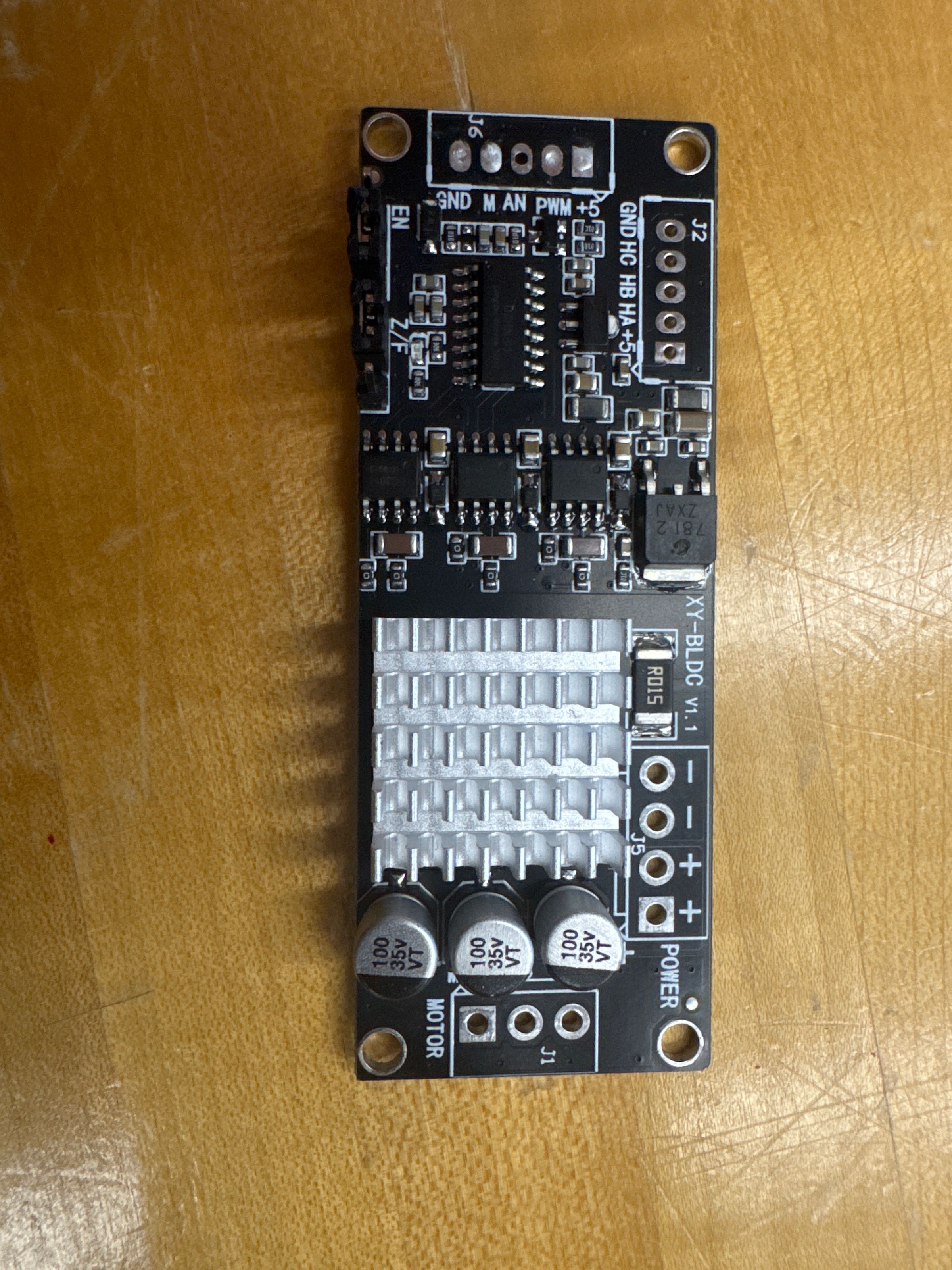
The ODESC V4.2 motor controller was selected for field-oriented control with bidirectional torque and regenerative braking over a simple UART ASCII interface. For a reaction wheel, rapid direction reversal is critical: a controller that coasts to zero before accepting a reverse command is too slow to balance. An earlier XY-BLDC controller was tried and discarded for exactly that reason.
The AS5047P magnetic encoder (14-bit absolute) provides rotor position feedback to the ODESC for FOC. Custom mounts for electronics, sensors, and the reaction-wheel assembly were modeled in OnShape and 3D printed.
Embedded Debugging and Hardware Bring-Up
Three embedded failures shaped the final design. Each forced me to stop trusting generated CubeMX defaults and verify timing, modes, and transaction behavior directly against the datasheets.
USB CDC enumeration failure. The STM32 would not enumerate as a USB device. The root cause was a PLL misconfiguration: the Black Pill board uses a 25 MHz external oscillator instead of the 8 MHz that CubeMX assumed, so the USB clock was wrong by default. Recalculating the PLL chain manually (PLLM=15, PLLN=144, PLLP=DIV4, PLLQ=5) restored the correct 48 MHz USB clock. This was the debug channel for all subsequent firmware work.
SPI communication corruption. The IMU was returning garbage with no consistent pattern. CubeMX had configured the wrong SPI mode: the ICM-45686 requires Mode 3 (CPOL=1, CPHA=1), and chip select had to stay low for the full transaction rather than toggle per byte. Both were wrong simultaneously, making the output look random. Correcting both resolved it.
Motor controller direction switching. The XY-BLDC controller required the motor to coast to zero before accepting a reverse command. For a reaction wheel, that delay makes balance correction far too slow.
Results
The balancing subsystem works: the bike maintains stationary upright balance indefinitely under normal test conditions. The STM32F411 runs a 400 Hz bare-metal PID loop that reads the IMU, estimates lean angle, computes a torque command, and drives the reaction wheel through the ODESC motor controller.
Verified:
- Indefinite stationary balance under normal test conditions
- 400 Hz bare-metal control loop on STM32F411
- IMU sampling and complementary-filter angle estimation at 400 Hz
- UART torque-mode control of the ODESC motor controller
- Safety shutoff when lean exceeds 0.5 rad (~29°)
- Recovery from small manual disturbances
Not yet quantified:
- Disturbance rejection range
- Reaction wheel speed during recovery
- Control-loop timing jitter
- Long-duration reaction-wheel saturation behavior
| Metric | Value |
|---|---|
| Control loop frequency | 400 Hz |
| Cycle time | 2.5 ms |
| Safety shutoff threshold | 0.5 rad (29°) |
| Reaction wheel motor peak torque | 6.6 Nm |
| Gravitational torque at 3° lean | ~3.7 Nm |
| IMU sampling rate | 400 Hz |
| Gyro range | ±125 dps |
| Accelerometer range | ±4g |
| Drive gear ratio | 8.2:1 |
Drive integration and autonomous navigation remain future work.
Reflections
Sensor fusion. The complementary filter works but has no model of sensor noise or dynamics. A Kalman or Mahony filter would give better angle estimates under vibration and rapid acceleration, at some implementation cost.
Lean setpoint calibration. The controller targets 0.0 rad (vertical), which assumes the center of mass sits directly above the contact points. That is never exactly true. An automated trim would improve steady-state performance without manual re-tuning.
Forward motion dynamics. At speed, lean angle and steering couple through frame geometry and gyroscopic effects. The current controller ignores this. Balancing while moving will require a more complete state-space model, such as LQR with the coupled lean-steer dynamics included.
Reaction wheel desaturation. If the wheel spins continuously in one direction, it saturates and loses correction authority. A strategy to bleed off angular momentum while near vertical would improve robustness over longer run times.
Report
The full write-up from the independent study: Self-Balancing Bike ISR Report (PDF).