
Overview
I worked across the fabrication and characterization of dye-sensitized solar cells (DSSCs), combining thin-film processing, electrochemical device assembly, scanning electron microscopy, and electrical testing. Our team compared candle-soot and pencil-graphite counter electrodes while keeping the TiO₂ photoanode preparation, N719 sensitizer, electrolyte, and illumination conditions consistent.
The objective was to evaluate accessible carbon coatings for photovoltaic devices and connect their electrical behavior to fabrication and assembly decisions. The soot-based device exhibited an approximately 17× larger illumination-induced current change at zero applied voltage than the graphite-based device. The graphite response identified electrode isolation as a priority for the next design iteration.
Device Architecture
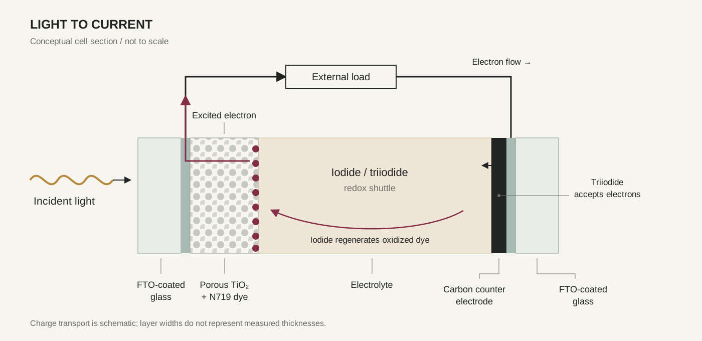
Each cell integrated a dye-sensitized TiO₂ photoanode and a carbon counter electrode on conductive glass. N719 absorbs incident light and injects excited electrons into the TiO₂. The FTO collects these electrons for transport through the external circuit, while the counter electrode supports the electrolyte reaction that regenerates the dye.
| Component | Function |
|---|---|
| FTO-coated glass | Transparent substrate and electrical current collector |
| Sintered TiO₂ film | Supports the sensitizer and transports injected electrons |
| N719 dye | Absorbs visible light and injects electrons into TiO₂ |
| Iodide/triiodide electrolyte | Regenerates the dye and transfers charge between electrodes |
| Carbon-soot or graphite counter electrode | Provides a conductive surface for triiodide reduction |
Fabrication
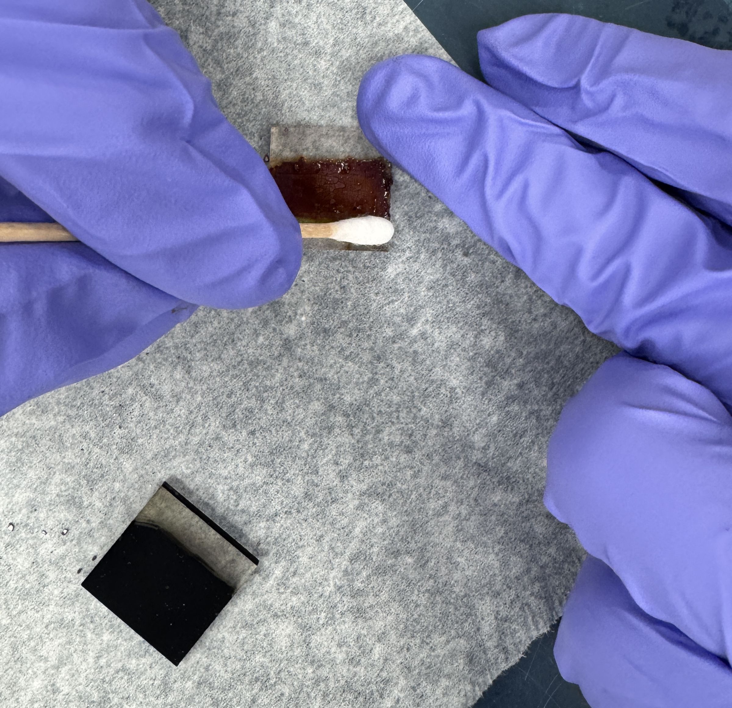
We applied TiO₂ paste onto FTO-coated glass using tape guides and a razor blade to define the deposited film. The electrodes were sintered at 450 °C for five hours and sensitized with N719 dye.
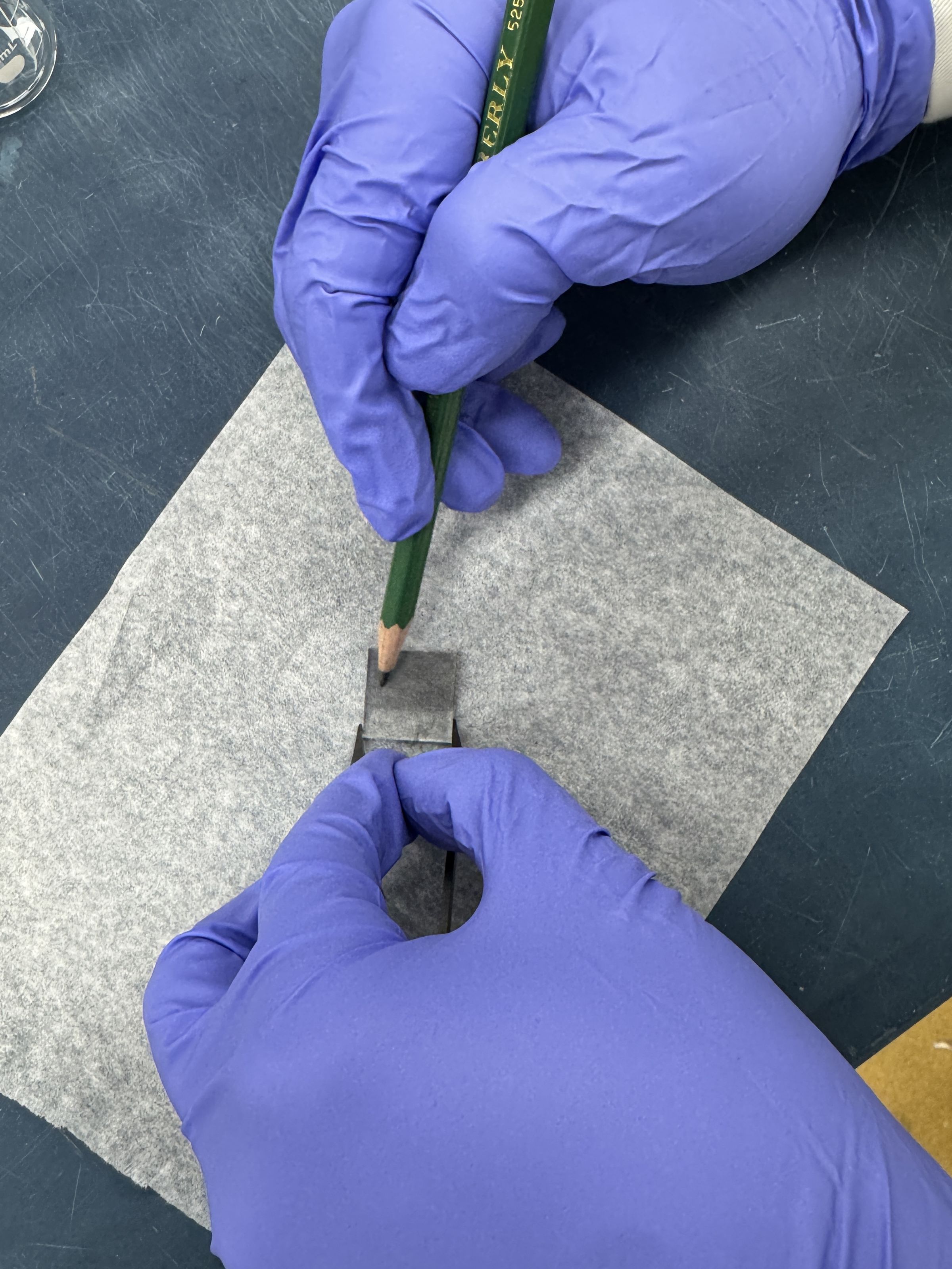
The counter electrodes used two deposition methods: flame deposition of candle soot and overlapping pencil strokes to build a graphite coating. The graphite electrode was baked at 300 °C for 15 minutes to remove organic binders. Exposed FTO regions provided electrical connection points outside the active coating.
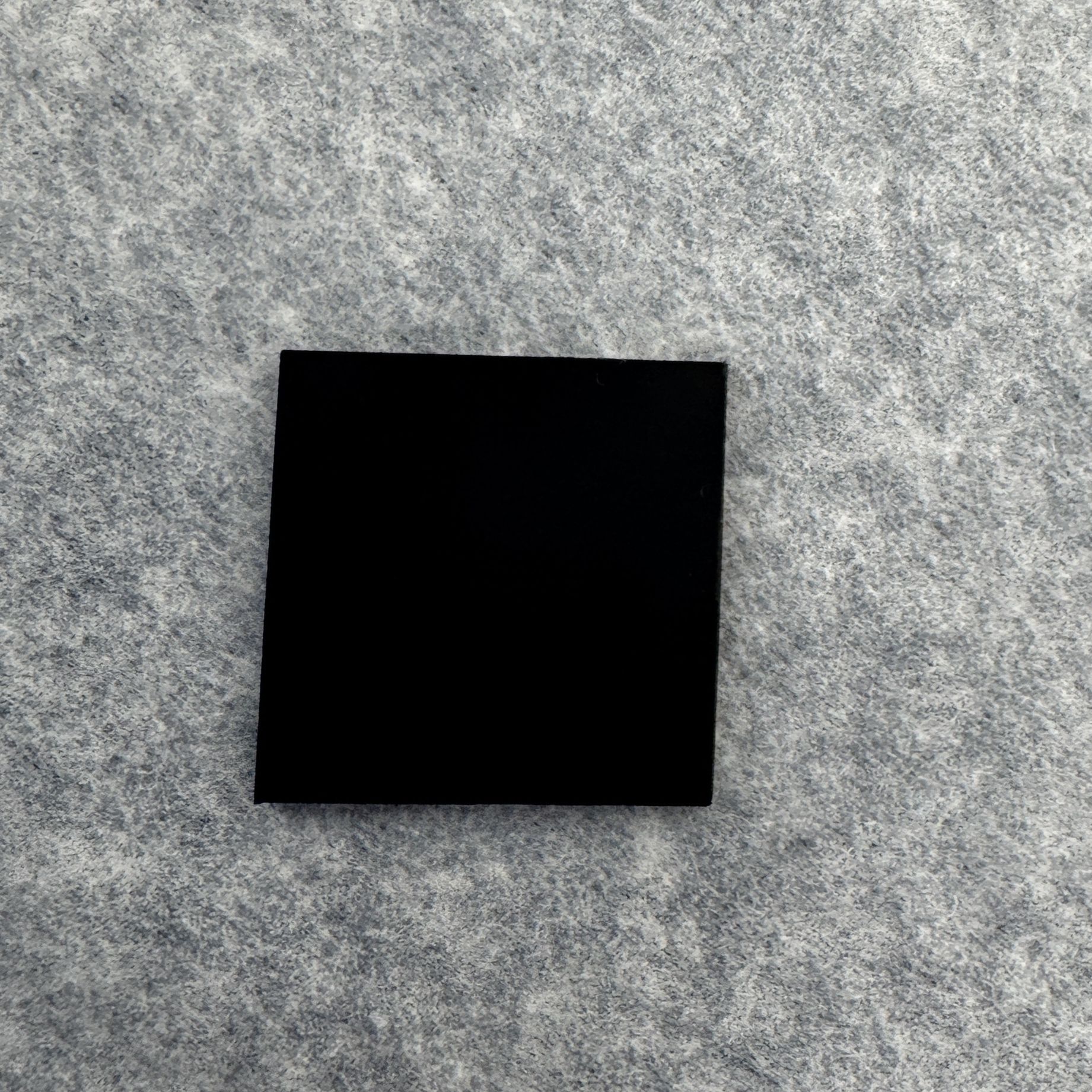
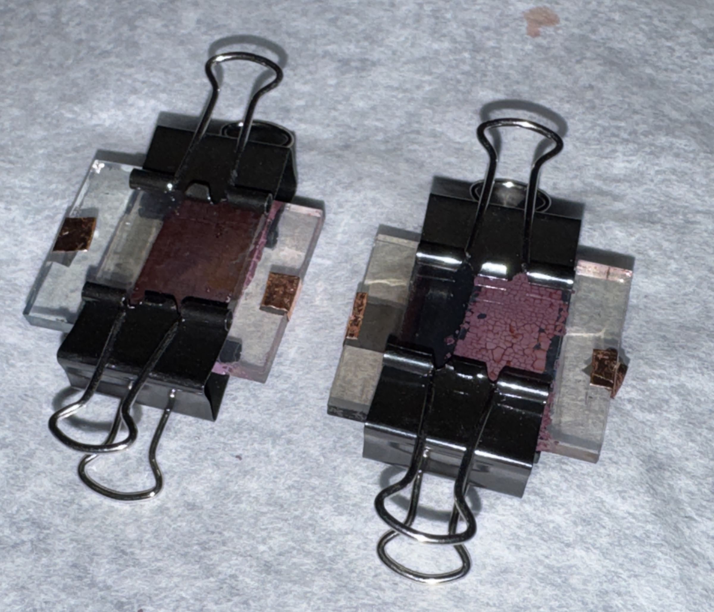
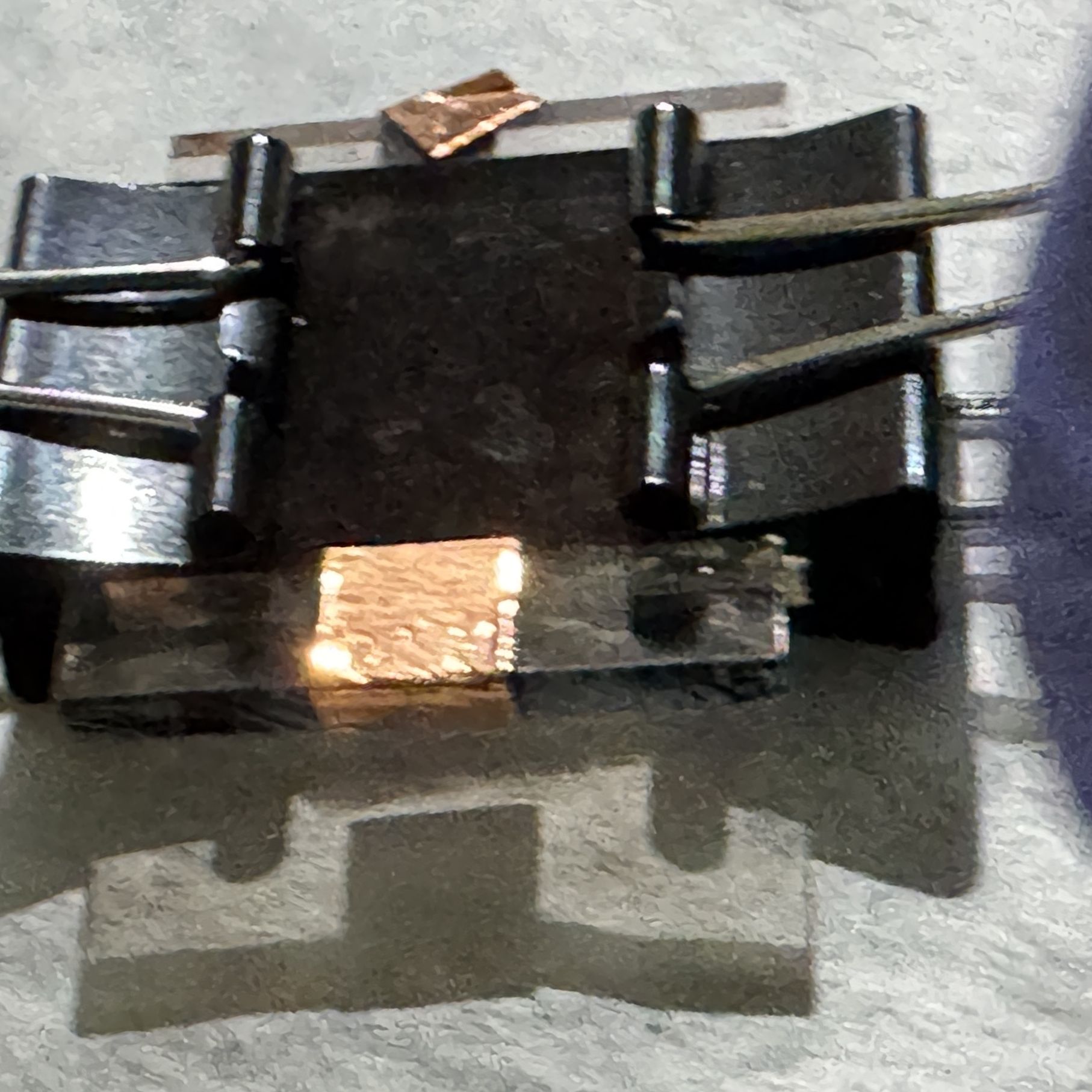
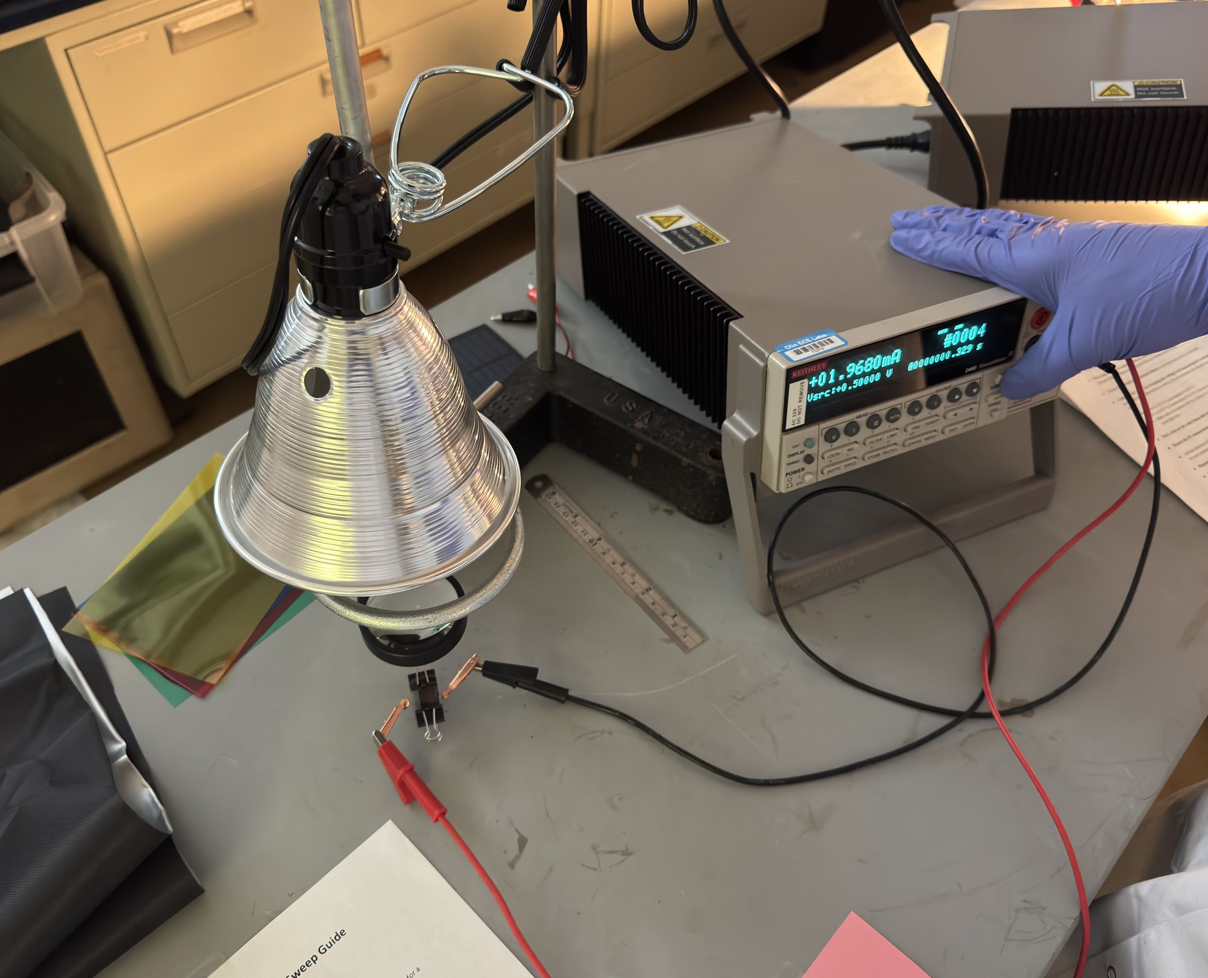
We assembled the cells with electrolyte between the coated surfaces, offset the glass substrates to expose the contacts, and secured the stack with binder clips. Copper contacts connected the FTO to the electrical test setup.
SEM Characterization
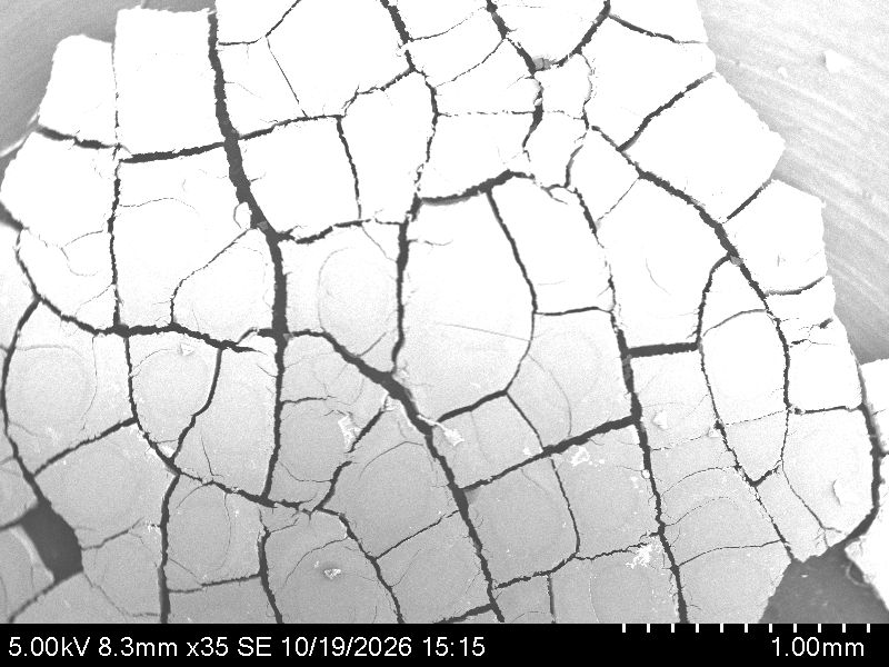
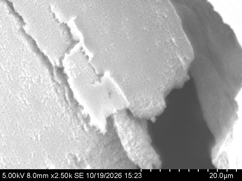
I used scanning electron microscopy to examine the TiO₂ film at multiple magnifications, assessing coating continuity, surface texture, and crack morphology.
At 35× magnification, the film exhibited a network of cracks separating the coating into distinct regions. At 2,500×, imaging resolved surface texture and the morphology of individual crack edges. These observations identified film continuity and mechanical handling as important considerations for device assembly.
Electrical Characterization
I used source-meter voltage sweeps to compare the dark and illuminated current–voltage responses of both devices. The lamp position, device orientation, and illumination setup were held consistent between tests. MATLAB analysis compared the measured curves and quantified the current change under illumination.
Results
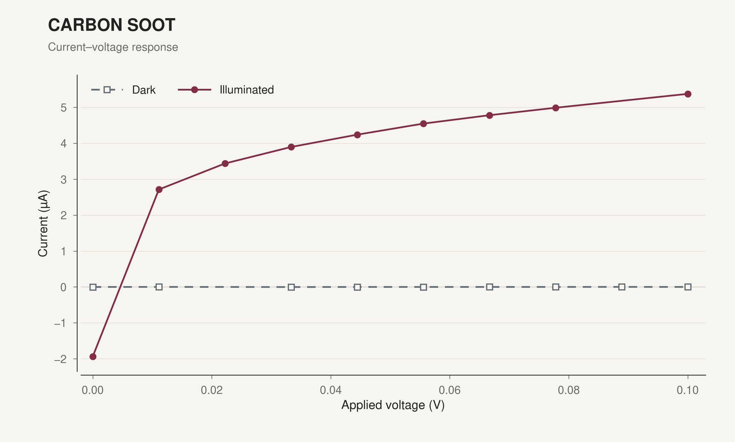
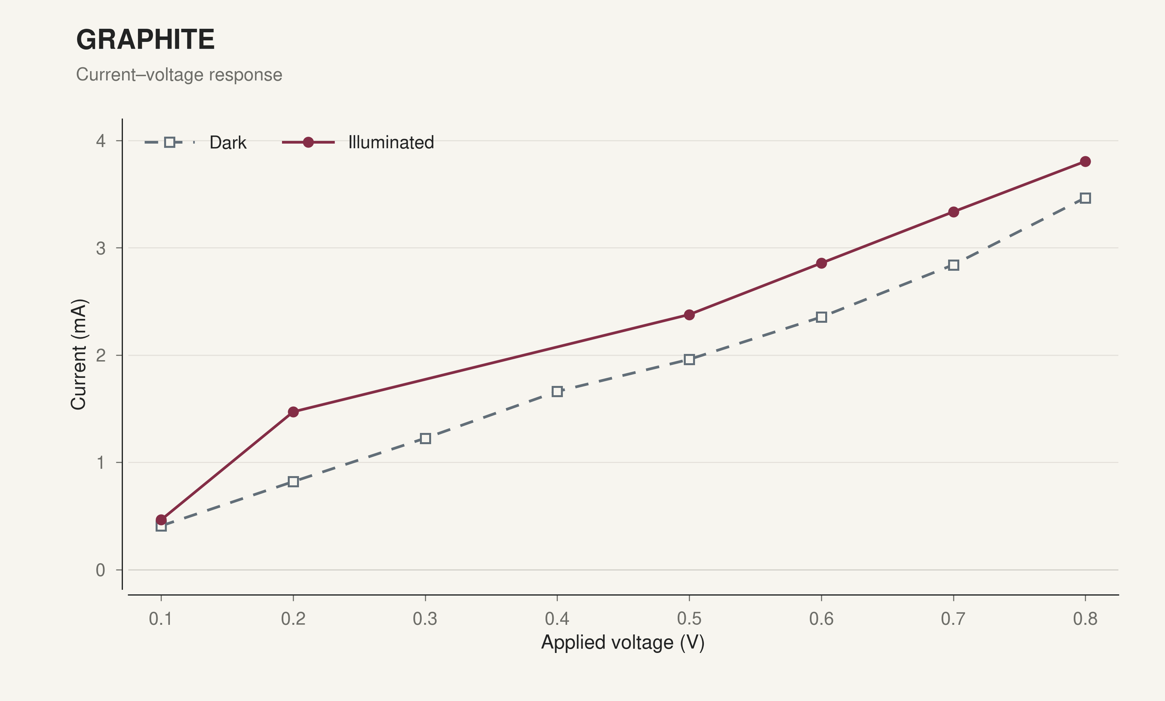
At zero applied voltage, the soot device showed a light-induced current change of 1.936 µA, compared with 0.117 µA for the graphite device. This corresponds to an approximately 17× stronger zero-bias light response in the soot-based cell.
| Counter electrode | Dark current at 0 V | Illuminated current at 0 V | Light-induced current change |
|---|---|---|---|
| Carbon soot | −0.001 µA | −1.937 µA | −1.936 µA |
| Graphite | −0.252 µA | −0.369 µA | −0.117 µA |
The graphite device exhibited substantial dark conduction and an approximately linear current–voltage response. This behavior is consistent with a parasitic conduction path and motivated a focus on electrode separation and short prevention. Cracking observed on the graphite-based device also made coating integrity and clamping pressure priorities for refinement.
The project connected material processing and SEM observations with device-level electrical measurements, turning the contrast between the two cells into specific assembly improvements.
Design Improvements
The next iteration would target electrical shunting in the graphite device through tighter control of electrode spacing, insulation, and assembly:
- Insulating spacer: Introduce an electrolyte-compatible perimeter gasket to maintain a defined gap and prevent direct contact between opposing conductive surfaces.
- Edge isolation: Insulate the electrode perimeter, keep the contact pads outside the sealed active area, and remove loose graphite particles before assembly.
- Controlled clamping: Apply uniform pressure around the perimeter to hold the stack securely while limiting local contact and additional film damage.
- Electrolyte containment: Meter the electrolyte inside the gasket and seal the perimeter to keep it away from exposed contact regions.
- Electrical verification: Check the dry assembly for direct continuity between electrodes before adding electrolyte, then use dark current–voltage measurements to screen the completed device for excessive leakage.
These changes would prioritize a well-isolated electrode stack, allowing the graphite counter electrode's contribution to the light response to be evaluated more effectively.